Discone VHF-UHF antenna - Educypedia
Discone VHF-UHF antenna - Educypedia
Discone VHF-UHF antenna - Educypedia

You also want an ePaper? Increase the reach of your titles
YUMPU automatically turns print PDFs into web optimized ePapers that Google loves.
®<br />
SEP 27 1997<br />
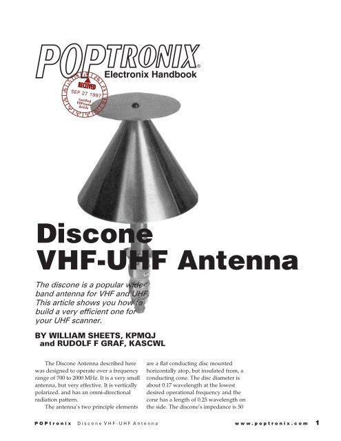
<strong>Discone</strong><br />
<strong>VHF</strong>-<strong>UHF</strong> Antenna<br />
The discone is a popular wideband<br />
<strong>antenna</strong> for <strong>VHF</strong> and <strong>UHF</strong>.<br />
This article shows you how to<br />
build a very efficient one for<br />
your <strong>UHF</strong> scanner.<br />
BY WILLIAM SHEETS, KPMQJ<br />
and RUDOLF F GRAF, KASCWL<br />
The <strong>Discone</strong> Antenna described here<br />
was designed to operate over a frequency<br />
range of 700 to 2000 MHz. It is a very small<br />
<strong>antenna</strong>, but very effective. It is vertically<br />
polarized. and has an omni-directional<br />
radiation pattern.<br />
The <strong>antenna</strong>'s two principle elements<br />
are a flat conducting disc mounted<br />
horizontally atop, but insulated from, a<br />
conducting cone. The disc diameter is<br />
about 0.17 wavelength at the lowest<br />
desired operational frequency and the<br />
cone has a length of 0.25 wavelength on<br />
the side. The discone's impedance is 50<br />
POPtronix <strong>Discone</strong> <strong>VHF</strong>-<strong>UHF</strong> Antenna www.poptronix.com 1
L<br />
θ<br />
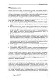
L=2953/F a<br />
MHz<br />
D=2008/FMHz<br />
θ=25º to 40º<br />
S=20% of coaxial line diameter or<br />
0.125 inch<br />
Where F=lowest frequency-700<br />
MHz selected, D=disc diameter,<br />
L=length of cone ellement, θ=<br />
angle of cone-selected value, and<br />
S=spacing-selected value<br />
S<br />
D<br />
DISC<br />
INSULATOR<br />
BRASS<br />
TUBE<br />
θ<br />
D<br />
L<br />
CONNECTOR<br />
b<br />
Fig. 1—DISCONE<br />
ANTENNA<br />
DIMENSIONS:<br />
a—view of idealized<br />
discone <strong>antenna</strong><br />
and b—view of<br />
assembled <strong>antenna</strong><br />
specified in this<br />
article. Equations<br />
can be used for<br />
assembled <strong>antenna</strong><br />
and provide excellent<br />
reception results.<br />
ohms, so it can be fed by a 50-ohm<br />
coaxial cable. The outer (shield)<br />
conductor is connected to the<br />
cone, the center conductor is<br />
connected to the disc. The<br />
<strong>antenna</strong>'s actual impedance varies<br />
depending on the cone's angle,<br />
frequency, and disc-to-cone<br />
spacing. Nevertheless, discone<br />
dimensions are not very critical for<br />
optimum performance.<br />
Figure 1-a is an idealized<br />
sketch of a true discone <strong>antenna</strong><br />
and its basic dimensions. It was<br />
determined that the disc diameter<br />
should be 3 inches and the length<br />
of a side element of the cone<br />
should be 4-1/4 inches. The angle<br />
(Fig. 1-b) could be any angle<br />
between 25 to 40 degrees, so 30<br />
degrees was selected for a<br />
practical reason.<br />
The space created by the<br />
insulating washer (S) will be 1/5 Of<br />
the inside diameter of the brass<br />
tube (Fig. 2) or about 1/8 inch<br />
(thickness is not critical).<br />
CONE<br />
BRASS<br />
ROD<br />
COAXIAL<br />
LINE<br />
50Ω<br />
Construction<br />
A piece of 5/8-inch brass tube is used<br />
to support the discone and is the outer<br />
conductor of the feedline (Figs. l-b and 2).<br />
This tube has an inside diameter of 19/32<br />
inch. With commonly available 1/4-inch<br />
brass rod used for an inner conductor, the<br />
section of coaxial line that results has a 52-<br />
ohm impedance.<br />
The exact impedance is not too critical<br />
and less than 10% variation in impedance<br />
should not cause reception problems. The<br />
length of the brass tube is up to the<br />
discretion of the builder. The loss due to<br />
the added length is negligible. A 5-1/2 inch<br />
length of brass tube was used in the<br />
discone illustrated here, but up to about<br />
two feet of tubing should present no<br />
problems. Longer lengths will require<br />
some mechanical modifications in order to<br />
ensure that the line geometry remains<br />
concentric and reasonably rigid. This<br />
becomes a construction problem and<br />
should be avoided.<br />
Theoretically, the cone of the discone<br />
should come to a point. However, it can be<br />
truncated to allow the brass tube to be<br />
soldered to it. The disc is fastened to the<br />
brass rod (Fig. 3) by a screw which fits into<br />
a tapped hole in the center conductor. A<br />
shoulder insulator made from plastic<br />
faucet washers keeps the brass rod<br />
concentric with the inner wall of the brass<br />
tube and provides a spacing between the<br />
disc and cone of about 0.125 inch. The<br />
bottom end of the line section is soldered<br />
to a type N <strong>UHF</strong> connector. A small clamp<br />
or U bolt can be used to mount the<br />
<strong>antenna</strong> to a mast.<br />
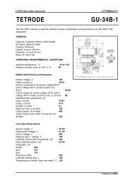
Sheet metal work<br />
The disc and cone were cut from 0.019-<br />
gauge copper flashing stock (Fig. 2)<br />
purchased from a local plumbing supply<br />
house. Since the angle selected is 30<br />
degrees, a half-circle pattern is needed to<br />
form the cone. Cut the cone and disc<br />
according to pattern. A little overlap tab, as<br />
shown in Fig. 2, allows for soldering after<br />
the cone is formed. Use shears and wear<br />
heavy gloves as copper tends to cut flesh<br />
with sharp razor-like edges. File all edges<br />
smooth.<br />
The cone is formed by first drawing<br />
radial lines on the inside surface, bending<br />
the pattern a little at each line around a<br />
block of wood or steel, and repeating the<br />
process until the pattern edges meet. The<br />
cone should be a fairly good, even, circular<br />
shape. Make sure the hole at the top will<br />
fit the 5/8-inch brass tube snugly. Clean the<br />
edges and soldering surfaces with fine<br />
(No. 0) steel wool. Clamp the edges of the<br />
cone together with the tab underneath and<br />
solder using 60/40 solid-core solder and<br />
liquid flux. Next, clean the brass tube with<br />
fine steel wool and solder the cone to the<br />
brass tube as shown in Fig. 3. Make sure<br />
the brass tube is symmetrical and<br />
concentric in the cone. Carefully clean all<br />
flux residues using hot water and baking<br />
soda, followed by a final rinse in hot water.<br />
Cut the brass rod to the same length as<br />
the brass tube. Drill a #36 hole in each end<br />
1/2-inch deep. Use a drill press if possible,<br />
and center punch each end to prevent the<br />
2<br />
POPtronix <strong>Discone</strong> <strong>VHF</strong>-<strong>UHF</strong> Antenna www.poptronix.com
drill from "walking". The rod has to be held<br />
by a vise or clamp to do this. Tap one end<br />
of the brass rod for a 6-32 screw thread.<br />
Make a shoulder-washer insulator as<br />
shown in Fig. 2 from two plastic washers.<br />
The top larger washer should be 3/4- inch<br />
diameter by 1/8-inch thick and<br />
the center hole should be large<br />
enough to pass a 6-32 screw (#28<br />
drill hole), but not larger than<br />
3/16 inch. The bottom washer<br />
should be press fit into the brass<br />
tube whose inside diameter is<br />
19/32 inch. The center hole<br />
should be 1/4-inch diameter to<br />
pass the 1/4-inch brass rod. Glue<br />
the washers together to form a<br />
shoulder washer. Now trial fit the<br />
entire discone assembly together.<br />
Trim the length of the center<br />
conductor so the top of the<br />
shoulder washer rests on the end<br />
of the brass tube. When the parts<br />
fit properly, you are ready to<br />
solder. Clean the brass rod and<br />
the rear of connector flange with<br />
fine steel wool. The surfaces<br />
should be shiny. Using 60/40<br />
rosin core solder, solder the<br />
untapped end of the brass rod to<br />
the type N <strong>UHF</strong> connector's<br />
center pin. Use at least a 100-watt<br />
soldering iron. Next, insert this<br />
assembly into the lower end of<br />
the 5/8-inch brass tube. Insert a 6-<br />
32 by 1/2-inch long, brass,<br />
roundhead screw through the<br />
center of the copper disc, the<br />
insulator, and into the tapped<br />
hole in the end of the brass rod. Tighten<br />
the screw enough to hold the parts<br />
together and hold them in place for<br />
soldering. Make sure the brass tube is<br />
centered on the flange of the connector.<br />
Now, solder the connector's flange to the<br />
brass tube all around the seam. Use only<br />
enough solder to do the job. Check for<br />
shorts with an ohmmeter. There should be<br />
an infinite resistance between the disc and<br />
cone, and the center terminal and flange of<br />
the type N connector. Next, check that<br />
zero resistance (short circuit) exists<br />
GLUE<br />
between the disc and the center terminal of<br />
the connector.<br />
Clean all flux residues and the discone<br />
construction is done. Alcohol is good for<br />
removing rosin flux. Clean with alcohol<br />
only outdoors and away from fire as<br />
3” DIA.<br />
BRASS TUBE<br />
(OUTER CONDUCTOR)<br />
5 1/2”<br />
COPPER DISK<br />
5/8” O.D.<br />
0.015”<br />
WALL<br />
5 3/8”<br />
SHOULDER WASHER<br />
INSULATOR<br />
HOLE<br />
#28 DRILL<br />
CUT FROM<br />
0.019”<br />
COPPER<br />
FLASHING<br />
1/4”<br />
#36 DRILL<br />
1/2” DEEP<br />
TAPPED 6-32<br />
THREAD<br />
#36 DRILL<br />
1/2” DEEP<br />
BRASS ROD<br />
(INNER CONDUCTOR)<br />
4 1/4”<br />
BEND EVERY 5–10º<br />
TO FORM<br />
CONE<br />
TOP WASHER<br />
DIA. 3/4” TO 1” WITH<br />
HOLE TO PASS<br />
#6 SCREW<br />
TAB AND<br />
OVERLAP<br />
SOLDER<br />
SEAM<br />
(INSIDE)<br />
BOTTOM WASHER<br />
O.D. TO FIN INSIDE OUTER TUBE<br />
I.D. IS 1/4” FOR BRASS ROD<br />
alcohol can be toxic and is highly<br />
flammable.<br />
If you have suitable equipment, check<br />
the <strong>antenna</strong>'s VSWR at the frequencies of<br />
interest. The prototype's measured VSWR<br />
was found to be better than 1.5 to 1 at 910<br />
and 1289 MHz. The use of type N<br />
connectors in the test cable setup is<br />
preferred.<br />
Mount it<br />
The discone can be mounted to a mast<br />
with clamps. Fasten clamps around lower<br />
1/4”<br />
FOR<br />
SOLDERING<br />
TAB<br />
5/8”<br />
PATTERN<br />
FOR<br />
CONE<br />
ELEMENT<br />
SOLDER<br />
TAB<br />
5/8” DIA.<br />
4 1/4” DIA.<br />
ASSEMBLED<br />
CONE<br />
Fig. 2.—<br />
CONSTRUCTION<br />
PARTS DETAILS for<br />
a 700-2000-MHz<br />
<strong>UHF</strong> discone<br />
<strong>antenna</strong>.<br />
POPtronix <strong>Discone</strong> <strong>VHF</strong>-<strong>UHF</strong> Antenna www.poptronix.com<br />
3
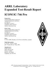
SCREW<br />
BRASS<br />
6-32 x 1/2”<br />
COPPER<br />
DISC<br />
SHOULDER-WASHER<br />
INSULATOR<br />
COPPER<br />
CONE<br />
reception at 900 MHz. This is probably<br />
because the home-built discone has a<br />
lower wave angle and because it is<br />
constructed of solid copper elements, with<br />
resulting lower losses. Improvement on<br />
reception and transmission was about 3<br />
dB. The discone was used with successas<br />
an <strong>antenna</strong> for experimental amateur TV<br />
transmissions at 900 and 1300 MHz.<br />
SOLDER<br />
TO TUBING<br />
BRASS<br />
TUBE<br />
SOLDERED ENTIRE CIRCUMFERENCE<br />
Fig. 3—ASSEMBLY<br />
VIEW of the discone<br />
<strong>antenna</strong>. Parts<br />
should fit firmly<br />
together before<br />
soldering is<br />
attempted. Clean<br />
surfaces to be<br />
soldered to a bright<br />
shine with #0 steel<br />
wool.<br />
BRASS<br />
ROD<br />
SOLDER TO CENTER PIN<br />
TYPE N CONNECTOR<br />
(UG – 58 A/U)<br />
end of brass tube, being careful not to dent<br />
or crush it. You can use small metal or<br />
plastic cable clamps as the <strong>antenna</strong> is very<br />
light, or it can be plugged directly into the<br />
scanner <strong>antenna</strong> jack. Use a right-angle<br />
adapter. When the <strong>antenna</strong> was used with<br />
a pocket scanner, excellent reception<br />
results were obtained on 860 and 935 MHz<br />
commercial signals, much better than the<br />
8-inch "rubber ducky" original equipment.<br />
Also, a marked reduction in<br />
intermodulation and cross modulation<br />
effects was noted. Although below the<br />
cutoff frequency, satisfactory 450-MHz<br />
reception was also obtained. For optimum<br />
450 MHz performance, increase the cone<br />
and disc dimensions 75%.<br />
In field tests, the discone assembled by<br />
the authors outperformed a 24-inch<br />
commercial discone sold for scanner<br />
LIST OF MATERIALS<br />
1—Brass tube, 5/8-in. (0.015-in. wall), 5-1/2-in.<br />
long<br />
1—Brass rod, 1/4-in., 5-3/8-in. long<br />
1—Copper or brass sheet, 0.019 to 0.030-in. thick,<br />
approximately 5 x 12 in.<br />
1—Type N <strong>UHF</strong> connector, UG58A/U, preferably<br />
silver plated<br />
2—Plastic faucet washers (3/4 to 1-in. dia.) with<br />
hole for #6 screw or smaller<br />
(drill and file to sizes in Fig. 2)<br />
1—6-32 x 1/2-in. brass machine screw, Philips or<br />
slotted head<br />
2—Pipe clamps to fit 5/8-inch OD tube (plastic<br />
preferred) for mounting<br />
<strong>antenna</strong>.<br />
Parts and materials not normally stocked by<br />
electronic parts stores can be obtained at hobby<br />
shops specializing in model aircraft and/or cars,<br />
plumbing supply outlets and hardware stores.<br />
A catalog describing kits for ATV transmitters,<br />
ATV receiving converters and other projects<br />
usable with the <strong>antenna</strong>s described in this article<br />
is available from:<br />
North Country Radio<br />
PO Box 53<br />
Wykagyl Station<br />
New Rochelle, NY 10804<br />
Please include a #10 SASE and $1.00 to cover<br />
handling and postage.<br />
E-mail: Ncradio200@aol.com or CompuServe<br />
102033,1572<br />
Copyright © 1997, POPtronix Inc.<br />
All rights reserved.<br />
As a service to readers, POPtronix, Inc. publishes available plans or information relating to newsworthy products, techniques<br />
and scientific and technological developments. Because of possible variances in the quality and condition of materials and<br />
workmanship used by readers, we disclaim any responsibility for the safe and proper functioning of reader-built projects<br />
based upon or from plans or information published online.<br />
Since some of the equipment and circuitry described in POPtronix, Inc. Project Articles may relate to or be covered by U.S.<br />
patents, we disclaim any liability for the infringement of such patents by the making, using, or selling of any such equipment<br />
or circuitry, and suggest that anyone interested in such projects consult a patent attorney.<br />
4<br />
POPtronix <strong>Discone</strong> <strong>VHF</strong>-<strong>UHF</strong> Antenna www.poptronix.com